
Conventional NDT
Non-Damaging, Cost-Effective, Ease of Application
Nondestructive testing (NDT) is a vital field comprising an array of inspection techniques used to evaluate materials, components, and systems without causing harm or permanent alteration.
These methods employ various principles from physics, chemistry, and mathematics to assess individual or group components.
The importance of NDT is underscored by several key benefits.
It allows the material or object being examined to survive the examination unharmed, leading to savings in money and resources enhancing safety; NDT methods allow for the thorough and relatively quick evaluation of assets, contributing to efficiency.
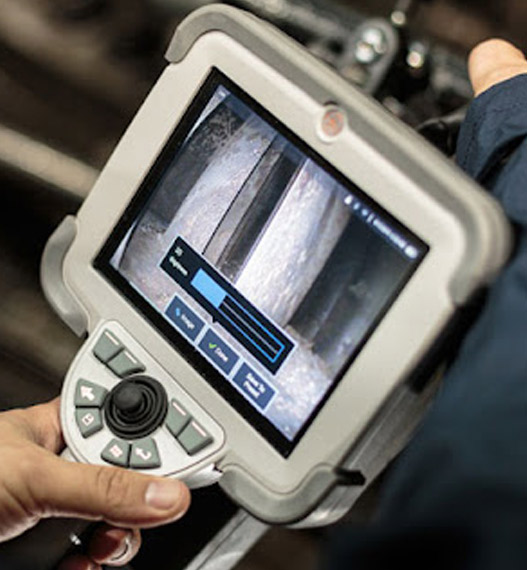
Visual Inspection (VT)
Visual Inspection (VT) is the oldest and most fundamental method of non-destructive testing (NDT).
It involves the direct observation of a component’s surface to identify any visible defects such as cracks, corrosion, misalignment, or other forms of damage. This technique is widely used across various industries due to its simplicity and effectiveness in detecting surface flaws.
Applications of Visual Inspection
Ensuring welds meet specified standards and identifying potential defects before they lead to failures.
Conducting inspections on tanks, pressure vessels, and process piping to ensure compliance with industry standards.
Monitoring manufacturing processes to maintain product integrity and safety.
Evaluating the condition of protective coatings on various surfaces.
Regular checks on lift/aerial equipment and other machinery to ensure operational safety.
Importance of Visual Inspection
Preliminary Assessment: VT often serves as a first-line inspection method that helps determine whether more advanced NDT techniques are necessary.
Ferrite Measurement
Ferrite measurement is a crucial aspect that evaluates the ferrite content in stainless steel and other alloys.
Several companies specialize in this service, providing accurate assessments to ensure material integrity and compliance with industry standards.
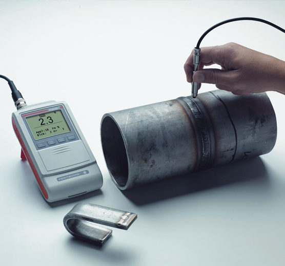
Methods of Ferrite Measurement
This is a widely used device for measuring ferrite content non-destructively. It operates by placing a probe on the material’s surface to measure its magnetic permeability, which correlates with the percentage of ferrite present.
This method involves creating a closed magnetic circuit around the material being tested. The permeability measured is then compared against standard values to determine the ferrite content.
Calibration pieces are utilized to ensure accuracy in measurements. These standards help maintain consistency across different tests and ensure compliance with industry regulations.
Importance of Ferrite Measurement
Material Properties: Ferrite content significantly influences the mechanical properties of stainless steel, including toughness, strength, and weldability. For instance, an appropriate amount of ferrite can help prevent issues like solidification cracking during welding.
Corrosion Resistance: The presence of ferrite affects the corrosion resistance of stainless steels. Inadequate or excessive ferrite can lead to susceptibility to stress corrosion cracking (SCC) and other forms of degradation.
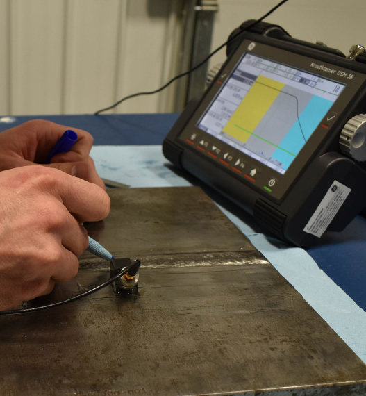
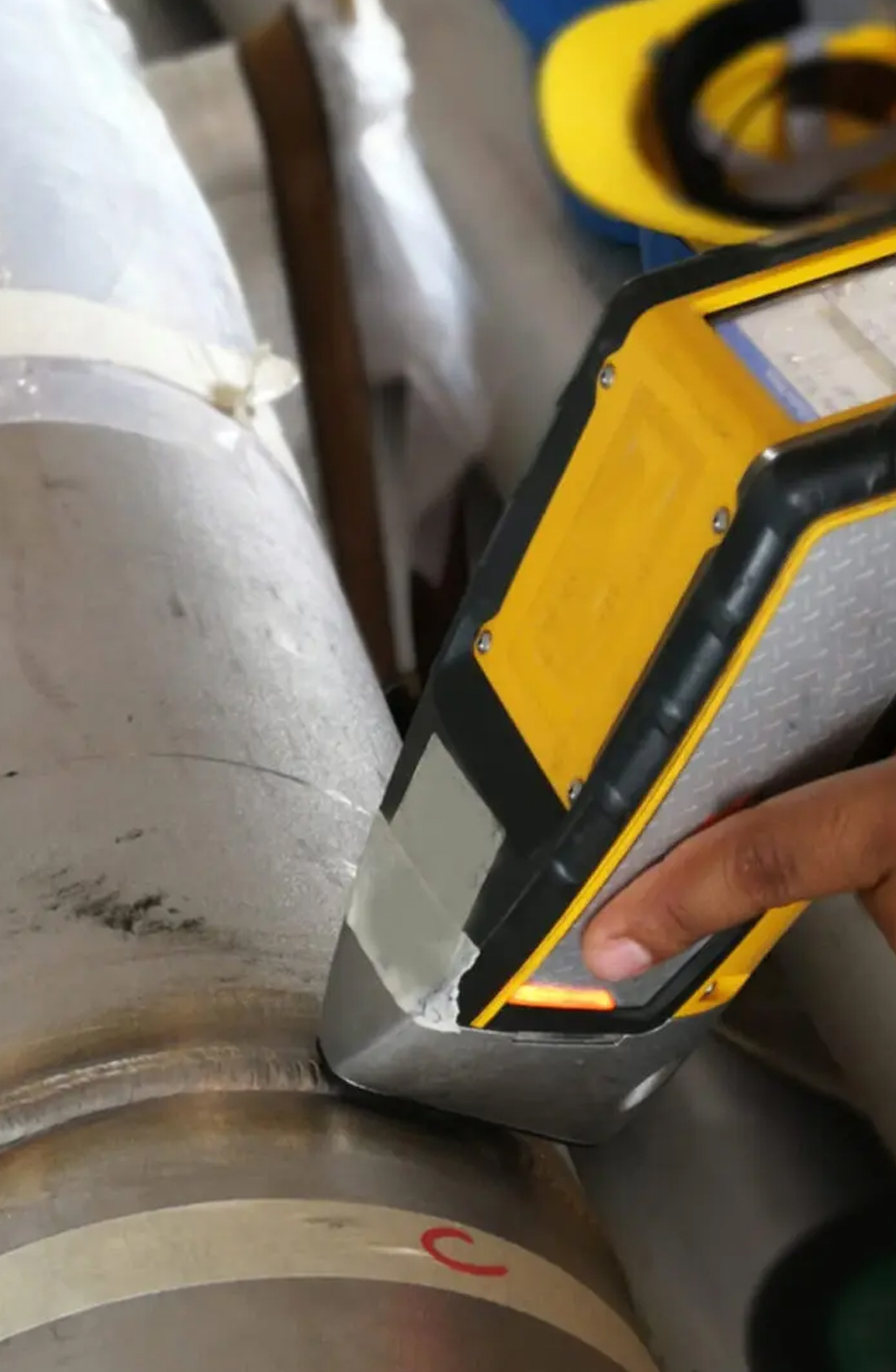
Ultrasonic Testing Shear wave (UT)
Applications of Shear Wave UT
Shear wave UT is predominantly used in industries where welding is common, such as construction, manufacturing, and oil & gas sectors. It allows inspectors to evaluate weld quality effectively by identifying internal defects that could compromise structural integrity

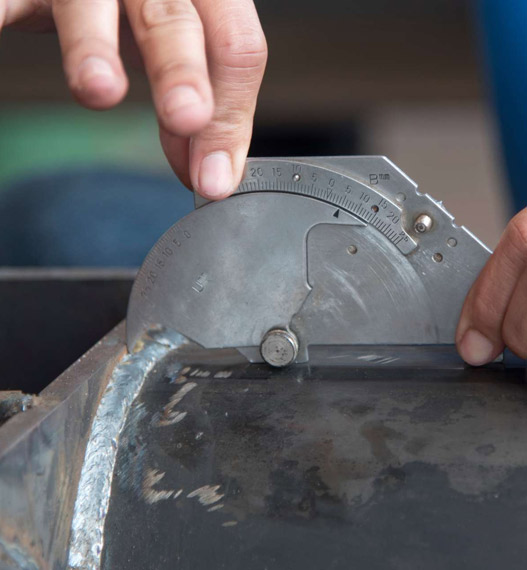
How Shear Wave Testing Works
Introduction of Ultrasonic Waves: In shear wave ultrasonic testing, an ultrasonic transducer generates sound waves that are directed into the test material at an angle. This is typically achieved using a wedge made of plastic or epoxy that helps to introduce the ultrasonic beam at a specific angle relative to the surface of the material
Detection of Flaws: As the ultrasonic waves travel through the material, they encounter different densities and acoustic velocities at various interfaces within the weld or base metal. When these waves hit a discontinuity—such as a crack or void—they reflect back towards the transducer. The time it takes for these echoes to return is measured and analyzed.
Advantages Over Straight Beam Techniques: Traditional straight beam ultrasonic testing is effective for detecting surface-breaking defects but often fails with welds due to their complex geometries and surface conditions. Shear wave testing is more suitable because it can detect flaws oriented in various directions relative to the surface.
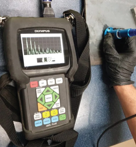
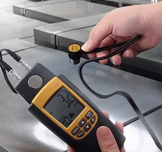
Ultrasonic Thickness Measurement (UTT)
Ultrasonic thickness measurement (UTT) is a widely used method that assesses the thickness of materials, primarily metals, by utilizing high-frequency sound waves. This technique is essential for evaluating the integrity and safety of various structures and components, such as pipelines, pressure vessels, and ship hulls.
Advantages of UTT
Non-destructive: It does not damage or alter the test piece during measurement.
Single-Sided Access: Measurements can be taken from one side only, making it suitable for inaccessible areas.
Real-Time Results: Technicians receive immediate feedback on measurements, allowing for quick decision-making regarding maintenance or repairs.
Versatility: UTT can be applied to various materials including metals, plastics, composites, and ceramics.
Applications of UTT
UTT is crucial for detecting corrosion or erosion in metal structures. By measuring remaining wall thickness, technicians can determine if maintenance or replacement is necessary.
It helps assess structural integrity in various applications including storage tanks, pipelines, and pressure vessels to ensure they can withstand operational conditions safely.
UTT can verify weld quality by measuring weld thickness against specified standards.
Regular inspections using UTT help organizations comply with safety regulations by identifying potential weaknesses before they lead to failures.
Limitations
For accurate measurements, surfaces may need cleaning or preparation to remove coatings or rust that could interfere with readings.
Each type of material requires specific calibration settings to ensure accuracy; improper calibration can lead to erroneous results.
Measurements may be less reliable on pitted or heavily corroded surfaces unless specialized equipment is used.
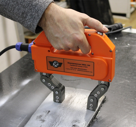
Magnetic Particle Inspection (MPI)
Magnetic Particle Inspection (MPI) is a widely used method that detects surface and near-surface discontinuities in ferromagnetic materials. This technique is particularly effective for identifying defects such as cracks, laps, seams, and inclusions in materials like iron, nickel, cobalt, and their alloys. The following sections outline the principles, processes, equipment, advantages, limitations, and applications of (MPI).
Limitations of MPI
MPI only works effectively on ferromagnetic materials such as iron and nickel; it cannot be used on non-ferrous metals like aluminum or magnesium.
After testing, components often need demagnetization to prevent interference with subsequent operations or electronic equipment.
While MPI can detect surface and near-surface flaws, it is not suitable for identifying deeper subsurface defects.
Advantages of MPI
Sensitivity: MPI is highly sensitive to surface and near-surface defects, making it effective for detecting very fine cracks that may not be visible to the naked eye.
Speed: The process is relatively quick compared to other NDT methods like radiographic testing (RT) or fluorescent penetrant inspection (FPI), allowing for rapid assessments.
Cost-Effectiveness: MPI is generally less expensive than many other non-destructive testing techniques.
Versatility: It can be applied to a wide range of ferromagnetic materials including steel and iron.
Applications of Magnetic Particle Inspection
MPI is utilized across various industries due to its effectiveness in ensuring component integrity. Common applications include:
- Aerospace components such as engine parts and landing gear.
- Automotive parts including axles and crankshafts.
- Structural steel inspections for bridges and buildings.
Oil and gas pipelines.
These applications highlight how critical MPI is in maintaining safety standards across multiple sectors
Liquid Penetrant Testing (LPT)
Liquid Penetrant Testing (LPT) also known as Dye Penetrant Testing (DPT), is a widely used method designed to detect surface-breaking flaws such as cracks, porosity, laps, and other discontinuities in non-porous materials.
This technique is particularly valued for its simplicity, cost-effectiveness, and ability to inspect large areas or complex geometries.
Principle of Liquid Penetrant Testing
The principle behind LPT relies on capillary action, where a liquid penetrant is drawn into surface-breaking defects. After applying the penetrant to the test surface and allowing it to dwell for a specified time, the excess penetrant is removed. A developer is then applied to draw out the trapped penetrant from defects, creating visible indications that can be inspected under appropriate lighting conditions.
Applications of Liquid Penetrant Testing
LPT finds applications across various industries due to its versatility:
- Inspection of welds for cracks or porosity.
- Detection of casting defects like shrinkage cracks or cold shuts in foundries.
- Maintenance checks in aerospace industries (e.g., aircraft fleet maintenance).
- Examination of piping systems in nuclear power plants and other energy sectors.
- Quality control during manufacturing processes for automotive parts and tools.
Limitations of Liquid Penetrant Testing
- Only detects surface-breaking flaws; subsurface defects remain undetected.
- Not suitable for porous materials as they absorb penetrants indiscriminately.
- Requires thorough pre-cleaning; contaminants can interfere with results.
- Environmental factors like temperature can affect performance—optimal testing temperatures range between 27°C and 49°C.

Advantages of Liquid Penetrant Testing
- Can detect very small surface-breaking flaws (as narrow as 150 nanometers).
- Applicable to both metallic and non-metallic materials provided they are non-porous.
- Cost-effective with minimal equipment requirements compared to other NDT methods like radiographic testing or ultrasonic testing.
- Suitable for inspecting complex geometries and large areas quickly.
- Provides clear visual indications that help assess defect size and location.
Positive Material Identification (PMI)
Positive Material Identification (PMI) is a critical method used to verify the chemical composition of metals and alloys. This process ensures that materials conform to specified standards and specifications, which is essential for quality control and safety compliance across various industries.
Methods of PMI
There are several techniques employed for Positive Material Identification:
Description: XRF is the most commonly used method for PMI due to its portability and ease of use. The handheld device emits X-rays onto the material being tested; the material then emits secondary X-rays that are characteristic of its elemental composition.
Advantages: It provides rapid results and can be used on-site without extensive preparation.
Limitations: While effective for many elements, XRF cannot detect lighter elements such as carbon, which limits its ability to differentiate between certain grades of stainless steel.
Description: OES involves creating a spark between an electrode and the sample material, exciting the atoms and causing them to emit light at specific wavelengths. This light is analyzed to determine the elemental composition.
Advantages: OES can detect almost all elements, including carbon and lighter elements, making it suitable for comprehensive analysis.
Limitations: The equipment tends to be larger and less portable than XRF devices, requiring more setup time.
Other methods like Laser Induced Breakdown Spectroscopy (LIBS) may also be utilized but are less common compared to XRF and OES.
Importance of PMI
Quality Assurance: PMI plays a vital role in ensuring that the materials used in manufacturing processes meet the required specifications. This is particularly important in industries such as oil and gas, power generation, aerospace, and pharmaceuticals, where material integrity is crucial for operational safety.
Preventing Failures: By confirming the correct alloy compositions, PMI helps prevent potential failures that could arise from using incorrect materials. For example, mismatched alloys can lead to issues like stress corrosion cracking or inadequate strength in welded joints, which are common causes of industrial accidents.
Regulatory Compliance: Many industries are subject to strict regulatory requirements regarding material use. Implementing PMI helps organizations comply with these regulations by ensuring that all components are made from appropriate materials.
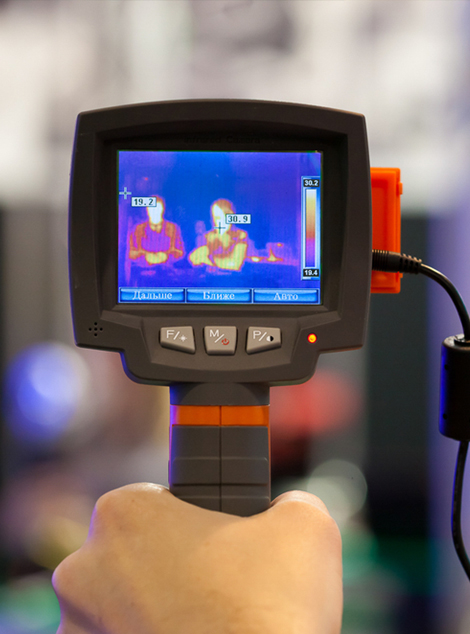
Infrared Thermography
Infrared thermography is a technique that utilizes thermal imaging to detect defects in materials by analyzing temperature variations on the surface of an object. This method has gained significant traction due to its ability to inspect large areas quickly and effectively, making it particularly valuable in industries such as aerospace, automotive, and civil engineering.
Advantages of Thermography Techniques
Speed: Rapid inspection capabilities allow for quick assessments over large areas.
Non-contact Methodology: It does not require physical contact with materials being tested, minimizing potential damage.
Real-time Results: Immediate feedback on material conditions helps facilitate timely decision-making regarding repairs or maintenance.
Types of Infrared Thermography Techniques
This method uses short bursts of high-intensity light (e.g., from flash lamps) to rapidly heat the surface of a test object. The subsequent cooling process is monitored using an infrared camera. Defects cause localized changes in cooling rates that can be detected.
n this technique, a periodic heating source is used to create a sinusoidal temperature variation on the surface. The phase shift between heating and response allows for enhanced detection sensitivity to subsurface defects
This combines ultrasonic excitation with thermal imaging. Ultrasonic waves generate localized heating at defect interfaces due to frictional effects, which can then be detected by infrared cameras.
A laser beam scans across the surface of a material, providing precise control over heating patterns and enabling effective detection of both horizontal and vertical cracks.
This method employs sinusoidal light patterns projected onto surfaces to create high-density thermal excitation for detecting fine defects in materials with high thermal conductivity.
Applications
Aerospace Industry: It is extensively used for inspecting aircraft components for fatigue cracks, delamination’s in composites, and other structural integrity issues
Automotive Sector: Used for detecting faults in vehicle bodywork and ensuring quality control during manufacturing processes.
Civil Engineering: Employed for assessing structural health in buildings and bridges by identifying hidden defects like voids or water ingress.
Manufacturing Processes: Useful for monitoring production lines for quality assurance by detecting flaws before products reach consumers.
Industries: Commonly used in aerospace, automotive, electronics, and medical device manufacturing.
Radiography Testing X –Ray & Gamma Ray (RT)
Radiography Testing (RT) is a widely used method that employs X-rays or gamma rays to inspect the internal structure of materials, components, or assemblies without causing any damage. This technique is particularly effective for detecting internal defects such as cracks, voids, inclusions, and other discontinuities in welds, castings, and other materials.
Principles of Radiography Testing
The fundamental principle of radiography testing involves the use of electromagnetic radiation (X-rays or gamma rays) to penetrate a material. The radiation passes through the object being tested and is captured on a detector or film placed on the opposite side. Variations in material thickness or density cause differences in radiation absorption, which are recorded as an image. These images reveal internal features and potential defects.
X-Ray Radiography
Source
X-rays are generated by X-ray machines using high-voltage electricity to accelerate electrons toward a metal target. When these electrons collide with the target material, X-rays are produced.
Applications
Material Thickness: X-rays are suitable for thinner materials due to their lower penetration power compared to gamma rays.
Precision: They provide high-resolution images and are ideal for applications requiring detailed inspection.

Tools and Techniques
Various tools and techniques are used in X-Ray radiography, including:
- film radiography
- digital real-time radiography.
Portable radiography devices now allow inspection of hard-to-reach and remote areas.
New digital real-time radiography systems provide accurate and real-time information, enabling operators to quickly detect and assess problem spots.
Advantages
- High-quality imaging with excellent resolution.
- Adjustable energy levels allow customization for specific applications.
- Safer than gamma rays due to controlled production.
Limitations
- Limited penetration depth compared to gamma rays.
- Requires access to electricity and bulky equipment.
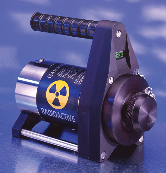
Gamma Ray Radiography
Source
Gamma rays are emitted from radioactive isotopes such as Iridium-192 (^192Ir), Cobalt-60 (^60Co), or Cesium-137 (^137Cs). These isotopes naturally emit high-energy photons during radioactive decay.
Applications
Thicker Materials: Gamma rays have higher penetration power than X-rays, making them suitable for inspecting thick materials like pipelines and heavy machinery.
Field Use: Portable sources make gamma radiography ideal for remote locations where electricity may not be available.
Industries: Widely used in oil & gas pipelines, shipbuilding, and construction industries.
Advantages
- High penetration capability allows inspection of dense or thick materials.
- Portable sources enable field inspections without reliance on electrical power.
- Effective over long distances.
Limitations
- Lower image resolution compared to X-rays.
- Safety concerns due to the use of radioactive materials requiring strict handling protocols.
- Limited lifespan of radioactive isotopes necessitates periodic replacement.